– The Comprehensive Lansulaser Guide for Industrial Buyers
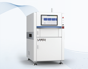
Fiber-laser systems have become the backbone of traceability, brand protection, and aesthetic customization for factories in electronics, automotive, medical devices, tooling, packaging, and dozens of other sectors. As a dedicated Chinese manufacturer with a 5 000 m² plant and more than one hundred patents, Lansulaser supplies configurable 20 W – 100 W fiber machines, CCD vision modules, rotary fixtures, and fully automated loading solutions to global B2B customers. This long-form guide (well over 1 500 words) condenses the essential know-how your engineers need to move from first power-up to lights-out production with confident, repeatable results.
1. Why Establish a Formal Laser Marking Workflow?
Many factories purchase a laser and then struggle to extract its full potential. Typical problems include:
- Inconsistent contrast on dark metals
- Excessive time lost when changing SKUs or fixtures
- Untapped automation options that keep labor costs high
- Documentation gaps that jeopardize ISO 9001 or FDA audits
A documented workflow—backed by software recipes and standardized fixtures—eliminates those pain points. Lansulaser customers who follow the procedure below routinely cut change-over from hours to minutes, slash consumable spending to zero, and raise OEE (overall equipment effectiveness) by double-digit percentages.
2. Fiber-Laser Technology in Plain Language
A diode-pumped ytterbium fiber generates a 1 064 nm infrared beam that travels through armored optical cable to a scan head. Two high-speed mirrors steer the beam through an F-theta lens, shrinking it to a 20 – 40 µm spot that instantly vaporizes, oxidizes, or anneals the top molecular layer of the target surface. Because the active medium is a sealed fiber coil, there are no flashlamps or fragile crystals to replace; service life commonly exceeds 100 000 hours. At Lansulaser we pair that robust engine with cast-aluminum frames, vibration-damping mounts, and closed-loop motors so the machine performs just as well inside a spotless medical-device cleanroom as it does on a dusty automotive line.
3. Pre-Operation Checklist: Safety, Environment, and Fixture Design
- Eye protection – Wear OD 6+ goggles rated for 1 064 nm.
- Enclosure integrity – Ensure all interlocks, polycarbonate windows, and light curtains function.
- Fume extraction – Run a dual-stage filter system before enabling the laser; metal fumes and polymer smoke are toxic.
- Cooling – Verify 15 °C – 22 °C water temperature (water-cooled) or unobstructed airflow (air-cooled).
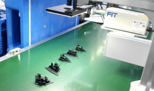
- Work holding – Design aluminum fixtures with locating pins or vacuum channels; maintain positional repeatability within ±0.05 mm.
- Surface prep – Wipe the marking zone with isopropyl alcohol; oil films reduce contrast and can pit the protective lens.
4. EZCAD Step-by-Step Operating Procedure
Step 1 – Launch and Create a Work Area
Open EZCAD 2 or EZCAD 3, click “New”, and set the workspace to the exact lens field size—commonly 110 × 110 mm, 175 × 175 mm, or 300 × 300 mm. Choose the origin (lower-left or center) to match your fixture datum.
Step 2 – Import or Draw Graphics
Import vectors (DXF, AI, PLT, SVG) for crisp edges, or bitmaps (BMP, PNG, JPG) at ≥300 dpi when necessary. Use EZCAD’s text tool to embed serial numbers, date codes, GS1 barcodes, or QR codes. Place elements in separate layers if you plan to apply different settings.
Step 3 – Enter Processing Parameters
Select a layer and enter four critical values:
- Power (%) – Controls pulse energy.
- Speed (mm/s) – Mirror scanning velocity.
- Frequency (kHz) – Pulse repetition rate.
- Hatch Spacing (mm) – Distance between adjacent fill lines.
Multiple hatches, angle rotations, and edge offsets improve solid-fill uniformity on large logos.
Step 4 – Red-Light Preview
Press “Red” (or F1) to project a visible-light outline onto the part. Check X/Y alignment relative to pins or clamp edges. Adjust position, rotation, or scale until the contour is perfect.
Step 5 – Focus the Beam
Manually turn the Z-axis hand-wheel or use Lansulaser’s motorized lift. Every machine ships with a dual-beam focus pointer; merge the two red dots into a single sharp point, or minimize the beam spot through the built-in focus gauge.
Step 6 – First-Article Marking
Close the safety door and press “Mark” (F2). Observe the first sample for plume color, audible popping, edge sharpness, and discoloration. Coated metals should show bright white contrast; plastics should darken or foam without charring.
Step 7 – Recipe Optimization
If contrast is weak, raise power by 5 % or slow speed by 100 mm/s. If melting or burrs appear, do the opposite. Adjust hatch spacing ±0.01 mm to fine-tune grayscale on aluminum. Record the final parameters.
Step 8 – Save the Parameter File
Click “Save Para”, name the file after the SKU, and store it on a network drive. Operators can now load the recipe on future batches with one click.
Step 9 – Enable Dynamic Serialization
Open “Dynamic Text”. Choose auto-increment, date/time stamping, or external CSV/database integration. For high-speed lines, set “Laser On Delay” and “Laser Off Delay” to 0.05 ms to prevent broken characters.
Step 10 – Validate and Release to Production
Run at least five consecutive parts, then verify barcode grade or contrast ratio per your quality plan. Attach the recipe and signed-off samples to your production traveler or MES record.
5. Typical Processing Parameters for Ten Industrial Materials
All values assume a 30 W fiber source and a 160 mm F-theta lens. Use them as starting points; coating thickness, alloy composition, and desired depth will require fine tuning.
| Material | Power (%) | Speed (mm/s) | Frequency (kHz) | Hatch (mm) |
|---|---|---|---|---|
| Stainless Steel | 70 | 800 | 30 | 0.04 |
| Anodized Aluminum | 30 | 1500 | 25 | 0.06 |
| Raw Aluminum | 60 | 1000 | 30 | 0.05 |
| Carbon Steel | 80 | 700 | 35 | 0.04 |
| Brass | 65 | 900 | 28 | 0.05 |
| Copper | 85 | 600 | 40 | 0.04 |
| Titanium Alloy | 50 | 1000 | 20 | 0.05 |
| ABS Plastic | 15 | 1800 | 18 | 0.08 |
| Polycarbonate | 18 | 1600 | 20 | 0.08 |
| Coated Paperboard | 12 | 2000 | 25 | 0.10 |
6. Process Optimization Tips
- Low contrast on metal – Decrease hatch spacing or apply a second pass at 90 ° to the first.
- Polymer charring – Increase speed, raise frequency, and lower power; add nitrogen purge for extra clarity.
- Deep engraving for tooling plates – Enable “Loop” with 3–5 passes, reduce speed by 20 %, and blow compressed air to remove dross between cycles.
- Color annealing on stainless gifts – Use 10 %–20 % power, 5 kHz–15 kHz frequency, 50 – 200 mm/s speed, and keep focus within ±0.05 mm.
7. Routine Maintenance and Lens Care
Weekly:
- Clean the protective glass with 99 % IPA and lint-free swabs.
- Empty the fume extractor prefilter bin.
Monthly:
- Inspect fiber connectors for dust; reseat if necessary.
- Backup all EZCAD recipes to a secure server.
Quarterly:
- Replace HEPA and activated-carbon cartridges in the extractor.
- Verify scan-head calibration with Lansulaser’s dot-grid target.
Because the fiber source is sealed, you never have to align resonator optics or replace flashlamps, reducing downtime compared with lamp-pumped YAG or CO₂ lasers.
8. System Integration and Automation
Lansulaser controllers speak RS-232, TCP/IP, MODBUS, OPC UA, and EtherNet/IP. Our SDKs for C#, Python, and LabVIEW let you:
- Push order data and retrieve serialized ID numbers in real time
- Embed the laser in a robot cell or pallet-transfer line
- Link CCD vision to correct X/Y offsets automatically
- Trigger downstream label printers or inspection cameras based on laser confirmation signals
Customers using these features typically achieve ≤0.2 % scrap and recover ROI in under twelve months.
9. Frequently Asked Questions
Q: EZCAD does not show my corporate font.
A: Copy the .TTF file to C:\Windows\Fonts and restart the software.
Q: We swap fixtures daily and lose alignment.
A: Integrate dowel pins on each pallet or add the Lansulaser vision module; it finds fiducials and shifts the job file ±0.02 mm automatically.
Q: Can the laser mark curved objects?
A: Yes. Add a rotary axis for cylindrical parts or our 3-D dynamic-focus module for large height differences.
Q: Does higher power always mean faster speed?
A: Only if the material absorbs efficiently. Aluminum often saturates above 60 % power; you gain more throughput by optimizing frequency and hatch.
10. From First Sample to Full Production in Under One Hour
Factories that adopt the ten-step EZCAD method typically:
- Reduce first-article approval time from half a shift to fifteen minutes
- Shrink change-over on multi-SKU lines from ninety minutes to ten
- Cut marking cost per part to fractions of a cent by eliminating inks, pads, and tool wear
Pair those savings with Lansulaser’s optional auto-loader and SPC software and you can run unattended night shifts, boosting capacity without new headcount.
11. Why Industrial Buyers Choose Lansulaser
- Lower total cost of ownership – No consumables and energy draw under 0.8 kWh.
- Faster throughput – Scan speeds up to 12 000 mm/s.
- Regulatory peace of mind – CE, FDA, and ISO certificates plus more than one hundred patents.
- Responsive service – Remote troubleshooting within forty-eight hours and on-site visits for all major world regions.
- Future-proof automation – Plug-and-play interfaces for cobots, MES, and vision inspection.
12. Ready to Mark the Future? Contact Lansulaser Today
WhatsApp +86 18925707676
Wechat lansulaser668
Email info@lansulaser.com
Address No. 3 Baoyuan Road, Lianhu Village, Tangxia Town, Dongguan, Guangdong, China (Lansulaser)
Whether you need a single desktop coder for R&D or a full turnkey line with vision, conveyors, and database links, Lansulaser delivers precision marking and smarter manufacturing—on time, on budget, and backed by experts who speak the language of global industry.