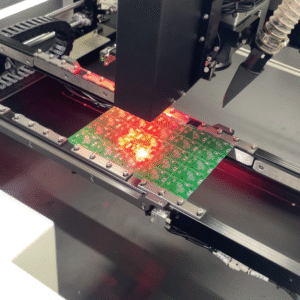


Every week, our Dongguan team receives inquiries missing the workpiece details a CCD laser marking machine 1 supplier actually needs. The result? Wrong quotes, wasted weeks, and frustrated buyers on both sides.
Prepare five core workpiece details for a CCD laser marking machine supplier: material composition, part dimensions and thickness, part shape (flat or curved), exact marking position, and batch format—whether parts arrive individually placed or fed continuously on a production line.
Those five points sound simple. But each one changes the camera setup, laser source, and fixture design CAD files 2. Let me walk you through why each detail matters and how to prepare it properly.
Last month, a buyer from Turkey sent us one blurry photo and asked for a price. Our engineers had to send back eleven questions before we could quote anything useful.
Share your part name, material type, exact dimensions including thickness, marking area size and location, marking content (text, QR code, logo), required mark depth or contrast, positional tolerance, and daily output target. These specifications let a supplier match the laser, lens, and camera correctly.

Think of your inquiry as a technical handshake. The more complete it is, the faster and more accurate the quote. In our experience exporting to markets like Italy, Germany, and the USA, complete first inquiries cut quoting time from two weeks to two or three days.
The Five Non-Negotiable Details
From years of building CCD solutions, we always start with these five data points before anything else:
- Workpiece material composition
- Workpiece dimensions and thickness
- Part shape—flat surface or curved surface
- Exact marking position on the part
- Batch format—single-piece placement or continuous line feeding
Miss any one of these, and the supplier is guessing. Guessing leads to wrong laser wavelength 3 choices, wrong field-of-view sizing, and quotes that get revised twice before an order.
Why Marking Area Dimensions Drive Lens Selection
Your marking area dimensions must match the machine's field of view. CCD systems commonly offer marking areas such as 100×70 mm, 100×100 mm, 175×175 mm, 200×200 mm, and 300×300 mm. If your part is 250 mm wide but you specify nothing, a supplier might quote a 175×175 mm system that physically cannot cover your mark. Bigger fields also reduce resolution per pixel, which affects camera recognition of small features.
| Specification | Why the Supplier Needs It | What Happens If Missing |
|---|---|---|
| Material composition | Determines laser wavelength and power | Wrong laser source, poor mark quality |
| Dimensions and thickness | Sets field of view and Z-axis travel | Lens mismatch, focus problems |
| Marking position | Guides fixture design and camera template | Marks placed on wrong face |
| Mark content and size | Sets resolution and readability targets | Unreadable codes, failed scans |
| Output target | Determines automation level | Under- or over-built machine |
Also state your positional tolerance. Some CCD visual-positioning machines achieve capture and marking accuracy in the ±0.02 to ±0.05 mm range, while certain UV/CCD systems advertise repositioning accuracy as tight as ±0.001 mm. If you need ±0.1 mm, you should not pay for ±0.001 mm hardware.
How Do I Describe My Workpiece Material and Surface Finish for Accurate Marking Results?
One trade-off we weigh constantly at our factory: a shiny anodized part marks beautifully with a fiber laser, but its surface reflectivity can confuse the camera during recognition.
Describe the base material precisely (stainless steel, aluminum, ABS, PC, PA, TPU) plus the surface condition: bare, anodized, plated, painted, oxidized, oily, reflective, or matte. Material determines laser wavelength; surface finish determines whether the CCD camera can reliably capture the part.
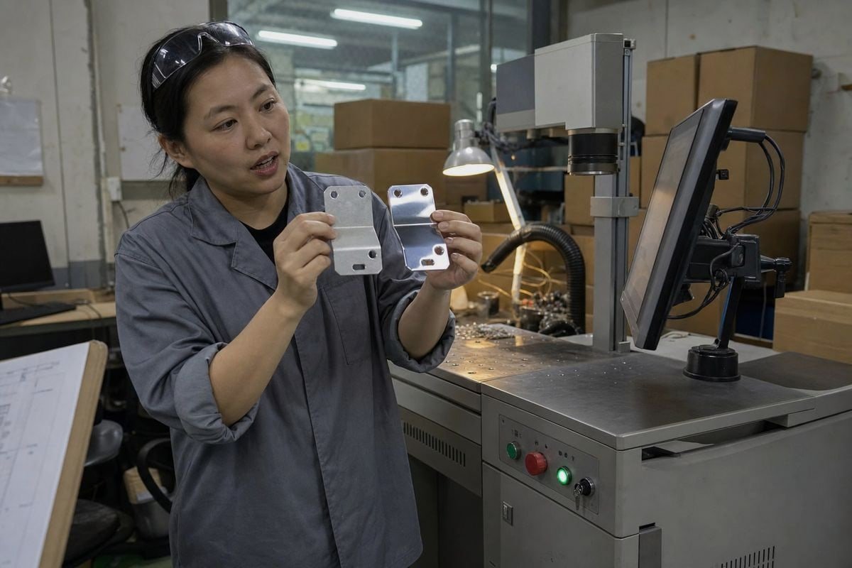
Material and surface finish are two separate answers, and buyers often give only one. Our solution engineers need both, because they affect two different subsystems: the laser and the vision system.
Material Determines the Laser Source
The laser wavelength must suit the material composition. Metals like stainless steel, aluminum, copper, brass, and titanium alloy respond well to fiber lasers. Plastics such as ABS, PP, PC, PA, and TPU often need UV or MOPA sources to achieve clean marks without melting or yellowing. On our production line, we test coated versus bare samples of the same alloy because a plated layer can change everything—the mark that looks crisp on bare aluminum may flake on a painted coating.
| Material Category | Typical Examples | Common Laser Choice | Surface Concern for CCD |
|---|---|---|---|
| Bare metals | Stainless steel, brass, titanium | Fiber laser | High surface reflectivity glares under lighting |
| Coated metals | Anodized, plated, painted parts | Fiber or MOPA | Coating color affects contrast ratio |
| Engineering plastics | ABS, PC, PA, TPU, PP | UV or MOPA | Transparent or dark parts blend into background |
| Mixed assemblies | Electronics, sensors, PCBs | UV, low power | Multiple textures in one camera frame |
Surface Finish Determines Camera Recognition
Here is a point many buyers miss. The CCD visual positioning system 4 must distinguish your part from its background. Highly reflective, transparent, or low-contrast surfaces can make recognition unreliable unless the supplier tests real samples. A matte black plastic part on a black conveyor belt is nearly invisible to a standard camera. We solve this with lighting adjustments, background changes, or higher-resolution cameras—but only if we know the surface condition in advance.
Also mention post-processing. If your parts undergo chemical cleaning or heat treatment after marking, say so. The mark must survive those steps, and that changes depth and contrast requirements.
What Sample Images or Drawings Should I Provide to Get a Precise Marking Quote?
A buyer from Italy once told me over WhatsApp: "Stella, I sent three suppliers the same photo and got three totally different machines quoted." His photo showed only the top face—the mark was on the side.
Provide clear photos from multiple angles, 2D drawings or CAD files (STEP or IGES preferred), a marking location diagram, examples of existing marks or labels, your required font and code format, and ideally two to five physical sample parts for camera and marking tests.
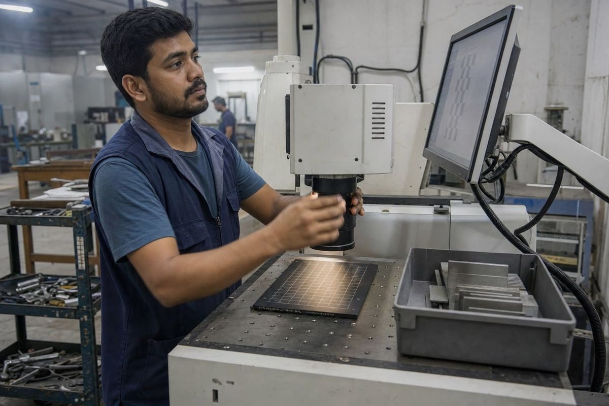
Files and samples are where good inquiries separate from vague ones. Photos help us understand shape and finish. Drawings give us dimensions and tolerances. Physical samples let us validate everything before you spend a single dollar.
The Ideal File Package
CAD file compatibility matters more than most buyers realize. When we receive a STEP file, our 20 solution design engineers can start fixture design the same day. From a photo alone, we can only estimate.
| Item | Format | Purpose |
|---|---|---|
| Multi-angle photos | JPG/PNG, in focus, good lighting | Shape, finish, and feature check |
| 2D drawing | PDF or DWG with dimensions | Tolerances and marking area dimensions |
| 3D model | STEP or IGES | Fixture design and curved-surface planning |
| Marking location diagram | Annotated photo or sketch | Exact mark placement and orientation |
| Existing mark sample | Photo or physical part | Target contrast, depth, and style |
| Code specification | Text description | QR, DataMatrix, serial logic, font size |
Show the Marking Position Explicitly
Never assume the marking position is obvious. Circle it on a photo. State the face, the offset from edges, and whether multiple faces need marks. If the part is curved or cylindrical, say so—curved surfaces need rotary fixtures or 3D marking heads, which changes the quote significantly. Flag any sensitive features to avoid: threads, holes, seals, connector pins, or cosmetic zones.
Fiducials Help the Camera
If your part has consistent geometric features—a hole, a corner, an edge—point them out. The CCD recognition template anchors on these features. Parts without stable visual anchors may need added fiducials or specialized lighting, and knowing this early avoids surprises at commissioning.
Finally, send physical samples before purchase. We run marking and capture tests on real parts and send back video proof. This step has saved buyers from wrong decisions more times than I can count.
Why Does My Production Volume and Batch Size Matter When Requesting a CCD Marking Solution?
Early in my time at our Dongguan factory, I learned a hard lesson: two customers with identical parts needed completely different machines—because one loaded parts by hand and the other ran a conveyor.
Production volume and batch format determine whether you need a simple manual-load station, a tray-based CCD system, or a full conveyor with random-position recognition. State your daily output, cycle time requirements, and whether parts arrive as single pieces or continuous line flow.

Batch format is the fifth detail on our must-have list, and it is the one buyers forget most often. The same laser and camera can sit inside very different machine architectures depending on how parts arrive.
Single Placement vs. Line Feeding
If your operator places one part at a time in a jig, positioning is semi-controlled and the CCD system mainly corrects small offsets. If parts flow down a conveyor in random orientations, the visual positioning system must capture, identify, and correct each part on the fly. That demands faster cameras—options like 7MP or 12MP sensors—stronger lighting control, and tighter software integration.
Consider these honest trade-offs before you commit:
- CCD systems add cost and calibration complexity. For uniform parts with stable, repeatable placement, a basic fixed jig may be cheaper and simpler. We tell buyers this directly, even when it means a smaller sale.
- High volume justifies automation. Conveyor integration, automatic feeding, and random-position capture pay off when daily output is high and labor alignment is too slow.
- Mixed or irregular parts favor CCD. Tiny screws, ICs, sensors, and special-shaped hardware are exactly where manual alignment fails and visual positioning shines.
- Data integration needs planning. If your marks carry dynamic serial numbers, tell the supplier about MES or ERP communication needs upfront. Retrofitting data links later is painful.
Match Cycle Time to Machine Design
State your target cycle time per part, not just daily volume. A 2-second cycle time may require a multi-head configuration or flying marking on a moving conveyor. A 30-second cycle time allows a simpler, cheaper station. Ambient factory lighting also matters at high speeds—strong overhead light can interfere with camera capture, so shielding or strobes may be needed.
Conclusion
Incomplete workpiece details cause wrong quotes, delays, and mismatched machines. Prepare material, dimensions, shape, marking position, and batch format upfront—then request a sample test before purchasing your CCD laser marking machine.
Footnotes
1. Comprehensive overview of laser marking technologies and their industrial applications. ↩︎
2. Provides technical standards for measurement, tolerances, and digital manufacturing file formats. ↩︎
3. Authoritative source for electrical engineering and vision standards used in laser systems. ↩︎
4. Explains the technology used by CCD cameras for imaging-based automatic inspection. ↩︎