


Buying a CCD laser marking machine before writing down factory marking requirements is the costliest mistake I see from our Dongguan workshop. The laser works. The line still stalls.
Define factory marking requirements for a CCD laser marking machine by documenting five elements: the material to be marked, the exact mark content, product dimensions and marking area, daily output and cycle time, and measurable quality criteria such as depth, contrast, and positional accuracy.
These five elements sound simple. In practice, each one hides decisions that change the camera, the lens, the laser source 1, and the software you need. This article walks through them in order, so you can hand a supplier a specification instead of a guess.
What Factors Should I Consider Before Buying a CCD Laser Marking Machine?
A purchasing manager in Turkey once sent me only a laser wattage and a budget. Our solution engineers sent back twelve questions before quoting anything.
Before buying a CCD laser marking machine, consider the purpose of the mark, the material and surface finish, the mark content and data source, required mark quality, real marking cycle time, part presentation, factory connectivity, laser safety, and total lifecycle cost.
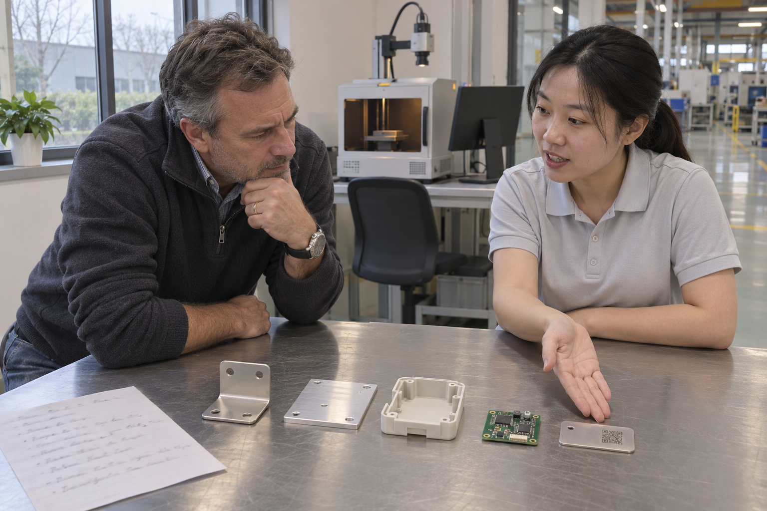
The wattage question is the last one we answer, not the first. A CCD laser marking machine is a process tool. The camera, the laser, and the software only make sense once the process is clear. So we start every project with the business reason for the mark.
Start with the purpose of the mark
Write down why your factory needs the mark. Common reasons include permanent product identification, serial numbers, lot and date codes, 1D or 2D barcodes, medical-device UDI labels, anti-counterfeiting, part orientation for assembly, and replacing paper labels or inkjet coding. The purpose decides how much the machine must do. A logo-only station needs to mark. A serialization station needs to position, mark, read back, grade, record, and reject. Those are different machines, even if the laser inside is the same.
The five questions our engineers ask first
Our 20 solution design engineers use the same checklist on every inquiry. It comes from years of fixing projects that skipped a step.
| Question we ask | What you should document | Why it changes the machine |
|---|---|---|
| What material? | Stainless steel, aluminum, plastic, copper, glass, coatings | Selects fiber, CO2, or UV laser source |
| What content? | Text, QR code, barcode, logo, serial number | Sets font, module size, data source, and software |
| What product size? | Length, width, height, marking zone | Sets CCD field of view and marking area |
| What output? | Parts per day, line takt, shifts | Sets marking cycle time and automation level |
| What quality? | Precision, clarity, depth, wear resistance, position consistency | Sets inspection method and acceptance criteria |
Marking, reading, grading, and traceability are four jobs
Buyers often treat these as one feature. They are not. Marking puts the code on the part. Reading confirms a scanner can decode it. Grading measures the code against a standard such as ISO 15415 for 2D codes 2 or ISO 15416 for 1D barcodes. Traceability stores the result with a part ID, timestamp, recipe version, and operator ID. Decide which of the four you need. Each one adds hardware, software, and cycle time.
A fair objection comes up here. Some buyers tell me a fixed fixture and a photo sensor would be cheaper than a visual positioning system. For a stable, single-SKU, high-volume part, they are right. A CCD vision system earns its cost when part placement varies, when you run many SKUs, or when you must verify every mark automatically. If none of those apply, I tell them so.
How Do I Determine the Right Marking Specifications for My Production Line?
Speed versus verification is the trade-off I weigh most often in our test bay. Adding a readback step after marking costs cycle time, but skipping it costs rejected shipments.
Determine marking specifications by measuring product size and marking area, setting the CCD field of view and positional accuracy tolerance, defining mark dimensions, depth, and contrast, calculating full marking cycle time against daily output, and fixing an acceptable defect rate.

A specification is a set of numbers you can test. "Fast and accurate" is not a specification. Below is how we turn a customer's product into numbers.
Measure the product and the marking window
Measure the product's length, width, and height. Then measure the marking zone itself. These two numbers set two different things. The product size sets the camera’s field of view. The marking zone sets the galvo marking area and lens. A common mistake is choosing a wide field of view for large parts and then expecting it to resolve a tiny 2D code. Resolution falls as the view grows. For small, high-precision parts, we often recommend a coaxial optical path 3, which removes parallax error. For wider detection of several parts at once, an off-axis camera can be the better fit.
| Specification item | Example value to define | Notes from our projects |
|---|---|---|
| Camera field of view | Covers full part plus expected drift | Larger view lowers pixel density |
| Positional accuracy | ±0.02 mm or looser as needed | Tighter tolerance needs coaxial optics and stable lighting |
| Rotation tolerance | Full 360° or limited range | Full rotation recognition adds processing time |
| Minimum code module | Smallest cell size of QR or Data Matrix | Must match laser spot size and camera resolution |
| Mark depth | Surface anneal, shallow etch, or deep engrave | Deeper marks cost cycle time |
| Lighting | Programmable ring or coaxial LED | Lighting matters more than camera megapixels |
Calculate the real marking cycle time
Supplier brochures quote laser exposure time. Your line pays for total cycle time. Count every step:
- Part arrives and presence is confirmed.
- Product identity is read by barcode or PLC.
- Recipe is loaded and data is validated.
- Camera acquires the image and calculates position.
- Laser applies the mark.
- Automated optical inspection verifies the result.
- Pass or fail is reported and the record is stored.
- Part is released or rejected.
Divide your daily output by available seconds per shift. Compare that takt with the total above, not just step five. If verification pushes you over takt, you have three options: a faster laser, a second station, or a lighter inspection. Pick the one your quality team can accept.
Write quality criteria you can measure
Define contrast, character clarity, depth, position tolerance, and wear resistance. Then state the test. For barcodes, require a grade under ISO 15415 or ISO 15416, not just a successful scan. A readable code can still fail the grade your customer demands. Also define the defect rate. Examples we use: zero unreadable safety-critical marks, no duplicate or skipped serial numbers, and no visible heat damage outside the marked zone.
One objection I hear often: "A higher-resolution camera will solve detection problems." It usually will not. Glare from polished aluminum or shadows in a recess defeat pixels. Programmable lighting and a protective, air-purged lens fix more problems than extra megapixels.
Which Materials and Products Will I Be Marking Most Often?
Last year our QC team marked two stainless-steel brackets from the same customer. One grade gave crisp black Data Matrix codes. The other turned brown.
List every material you mark, such as stainless steel, aluminum, copper, brass, titanium, ABS, acrylic, PVC, or glass, and rank them by volume. Material surface compatibility decides the laser source: fiber for metals, CO2 for organics, UV for heat-sensitive plastics.
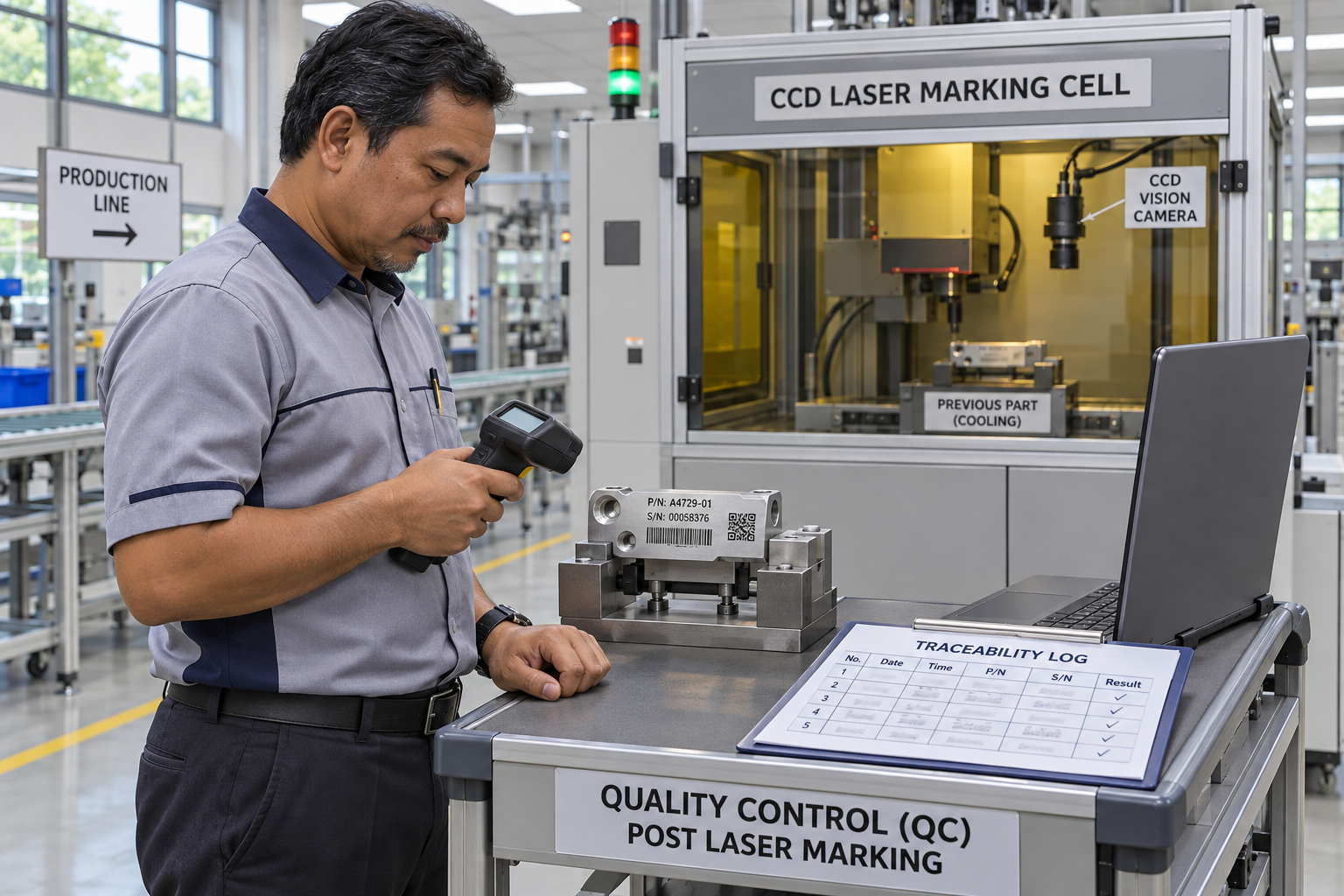
The two brackets taught us a simple rule. Test, never assume. The same fiber laser source can give high contrast on one alloy and a weak, discolored mark on another. The material profile is therefore the foundation of your requirement document.
Build a material profile for each product family
For every material, record the type, surface finish, color, hardness, and thermal sensitivity. Note whether the surface is polished, brushed, anodized, painted, oily, or textured. Note any coating that must stay intact. Then note what is not acceptable: smoke, residue, burrs, discoloration, or a heat-affected zone. These details steer the laser type, the power, and the pulse settings.
| Material group | Typical laser source | Common content | Watch-outs we see |
|---|---|---|---|
| Stainless steel, titanium | Fiber or MOPA fiber | Serials, Data Matrix, deep engraving | Alloy grade changes contrast; reflections affect camera |
| Aluminum, anodized aluminum | Fiber or MOPA fiber | Black marks on anodized, logos | Bare aluminum gives low contrast; MOPA helps |
| Copper, brass | Fiber, often higher power | Part numbers, logos | High reflectivity; test for heat spread |
| ABS, PVC, plastic housings | UV or MOPA fiber | QR codes, date codes | Fumes and foaming; UV lowers thermal damage |
| Acrylic, organics, packaging | CO2 | Batch codes, graphics | Edge melting; extraction required |
| PCB, electronic components | UV | Tiny 2D codes, traceability IDs | Very small modules need coaxial vision |
Match the product list to the industry rules
Your product list usually tells us the standard you must meet. Auto parts programs follow customer-specific identification rules. Medical devices need UDI-compliant codes, often structured under GS1 traceability standards. Aerospace and defense parts may call for MIL-STD-130 marking 4 and AS9100 record practices. Battery components and PCBs need very small, high-density codes that survive assembly and cleaning. Hardware tools need deep, abrasion-resistant engraving. Tell your supplier the industry, and the quality target becomes clearer.
Rank by volume, then by difficulty
Rank materials by how many parts you run per month. Then flag the hardest one. The machine must handle the hardest material at the volume of the most common one. If 80 percent of your parts are anodized aluminum and 5 percent are copper, we size the fiber laser source and vision for the aluminum takt, then verify the copper with test samples. We also ask customers to send parts that have gone through downstream steps like washing, plating, or heat treatment. A mark that looks fine off the laser can fade after sterilization.
How Can I Communicate My Factory Requirements to a Laser Marking Supplier?
I learned this lesson after a delayed Italian project: a drawing and a WhatsApp photo are not a specification. Now our team requests physical samples first.
Communicate factory requirements by sending a written specification package: production samples, drawings, mark artwork, material list, cycle-time target, data interface protocols, environmental conditions, and acceptance criteria. Then require sample marks, run-at-rate data, and FAT/SAT testing before final acceptance.
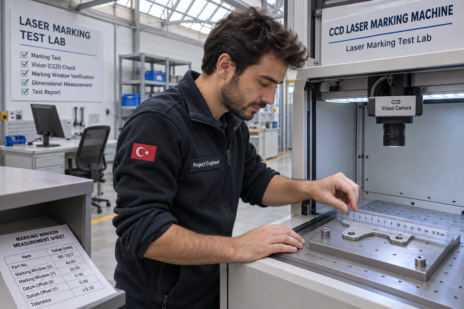
A good supplier will ask you for most of this anyway. A great buyer sends it before being asked. This saves weeks of back-and-forth and protects you from delivery delays caused by late changes.
Build the request package
| Item to send | What it should contain | Why the supplier needs it |
|---|---|---|
| Production samples | At least several parts per material and finish | Real marking tests and vision trials |
| Drawings and artwork | Part dimensions, marking zone, vector files in DXF or AI | Confirms marking area and content layout |
| Content and data rules | Font, character count, serial logic, code type, duplicate prevention | Defines software and data validation |
| Cycle-time target | Parts per hour, marks per part, shifts per day | Sizes laser, camera, and automation |
| Interface protocols | PLC brand, MES or ERP, SQL, OPC UA, digital I/O | Plans production line integration |
| Environment | Dust, oil, temperature, vibration, ambient light | Decides enclosure rating and lens purge |
| Acceptance criteria | Barcode grade, position tolerance, defect rate | Sets the FAT and SAT pass conditions |
Define production line integration clearly
Tell the supplier where the serial number comes from. It may be a PLC, an MES, an ERP, a database, an upstream barcode scanner, or an operator. The machine should never mark a part until that identity is confirmed. Write out the handshake: part arrives, identity is read, recipe is selected, data is validated, camera locates the mark area, laser marks, vision verifies, result is reported, record is stored, part is released or rejected. Also state what happens when the network drops, when a duplicate serial is requested, or when a mark is incomplete. Your industrial automation software must handle those cases without an engineer on site.
Some buyers worry about cloud-connected machines. Remote diagnostics help us support customers in Germany, Australia, and Saudi Arabia quickly. But if your IT policy requires offline production, say so up front. We can configure local logging and remote access that your team controls. The point is to raise this early, not after installation.
Ask for proof, not promises
Supplier authenticity is a real concern for buyers who find us on Google. The answer is evidence. Ask for sample marks on your actual parts, the parameter records used, vision inspection results, barcode-grade reports, and run-at-rate data. Ask the supplier to show deliberately rotated, dirty, and scratched parts, and to report both false accepts and false rejects. Then run a Factory Acceptance Test at the supplier's site with your approved parts and data. Follow with a Site Acceptance Test after installation, integration, and operator training. Also confirm laser safety classification for the complete enclosed machine, since a Class 1 rating applies to the integrated system, not the bare laser source.
Conclusion
Buy a CCD laser marking machine as a validated marking-and-traceability system, not an engraver. Define material, content, size, output, and quality first, then suppliers can quote accurately.
Footnotes
1. Fundamental principles and types of laser sources used in industrial and scientific applications. ↩︎
2. ISO standard for bar code print quality test specifications for two-dimensional symbols. ↩︎
3. Technical explanation of coaxial optical systems used to improve precision and reduce parallax in imaging. ↩︎
4. Department of Defense standard for the identification marking of U.S. military property. ↩︎