


Defining requirements for an industrial automation laser marking machine tripped up many buyers I’ve met. On our production floor in Dongguan, I’ve watched rushed specs turn into costly retrofits.
To define requirements for an industrial automation laser marking machine, specify the mark content, material, marking area, cycle time, laser source, integration protocols, and safety needs first. Confirm your product suits standard marking, keep content under 300mm×300mm, and verify marking time fits your line speed.
Below, I break this down into four practical questions. Answer them in order, and your requirements document almost writes itself. Let’s start with your production line.
What Factors Should I Consider Before Choosing a Laser Marking Machine for My Production Line?
A buyer from the Philippines once sent our team a photo of her product and asked, "Can you mark this?" That single photo saved her weeks, because our engineers spotted a fit problem immediately.
Before choosing a laser marking machine, confirm your product accepts a standard marking process, verify the mark content fits within 300mm×300mm, and check that marking time matches your cycle time requirements. Products failing any of these three checks are poor candidates for industrial automation marking.
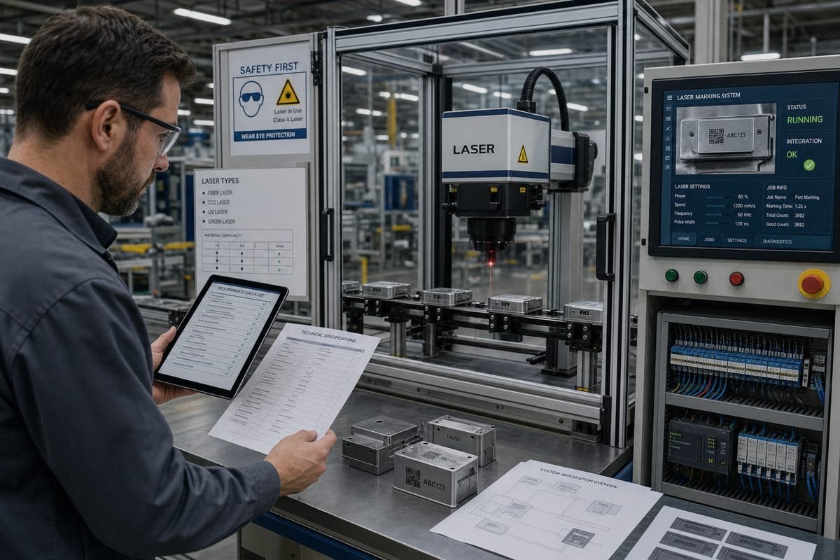
These three checks come directly from years of quoting automation projects at our factory. Most failed projects fail on one of them, so I always run them first, before any talk about wattage or price.
Check One: Is Your Product Suitable for Standard Marking?
Not every product marks well with a standard machine. Highly reflective surfaces, deeply recessed marking zones, and unusual coatings can all cause trouble. Material thermal conductivity 1 matters too. A metal that pulls heat away fast needs different parameters than a heat-sensitive plastic that scorches easily. We always ask customers to send samples before we commit to a solution. A test mark tells the truth faster than any datasheet.
Check Two: Is the Mark Content Within 300mm×300mm?
Marking field dimensions have real physical limits. Standard galvo scanning heads 2 cover a defined area. Once your content exceeds 300mm×300mm, a single-station automated marker becomes impractical. You would need a moving axis, a splicing system, or a 3D large-format machine, and those change the whole automation design. My advice is simple: measure your mark, not your part.
Check Three: Does Marking Time Fit Your Line?
If one mark takes 40 seconds but your conveyor delivers a part every 8 seconds, the math never works. Long marking content, deep engraving, or dense 2D codes all stretch cycle time. Either shorten the content, split it across stations, or accept that automation is not the right fit.
| Suitability Check | Pass Condition | Fail Consequence |
|---|---|---|
| Product compatibility | Standard laser marks material cleanly | Custom fixtures or different technology needed |
| Mark size | Content fits within 300mm×300mm | Automation becomes complex and costly |
| Marking time | Mark completes within takt time | Line bottleneck; automation loses its value |
How Do I Determine the Right Laser Type for My Industrial Automation Needs?
Our sample room holds shelves of customer parts, from anodized aluminum 3 to clear medical plastics. Every shelf tells the same lesson our engineers repeat daily: the material picks the laser, not the buyer.
Determine the right laser type by matching your material's absorption characteristics: fiber laser sources suit most metals, CO2 lasers handle organics like wood and leather, UV lasers mark heat-sensitive plastics and glass, and MOPA fiber lasers produce colored marks on stainless steel and black marks on anodized aluminum.
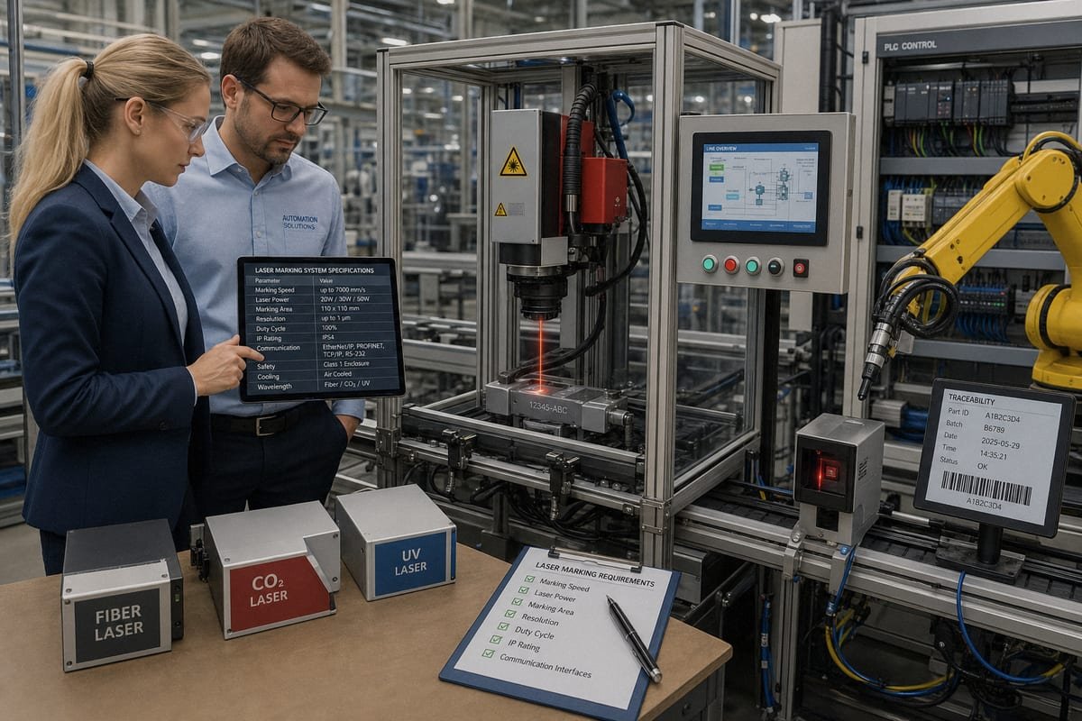
Here is a quick comparison to make the choice scannable:
| Laser Type | Best Materials | Typical Automation Use | Marking Character |
|---|---|---|---|
| Fiber laser | Steel, aluminum, brass, engineering plastics | Metal part serialization, tool marking | Deep, permanent, high contrast |
| MOPA fiber | Anodized aluminum, stainless steel | Black logo marking, color marking | Adjustable pulse, gentle on coatings |
| CO2 laser | Wood, leather, paper, glass, some plastics | Packaging date codes, non-metal lines | Fast surface marking on organics |
| UV laser | Heat-sensitive plastics, glass, silicone, PCB | Medical, electronics, cosmetics | Cold marking, minimal heat damage |
Why Absorption Beats Wattage
A laser only marks what its wavelength can be absorbed by. That is why a 100W fiber laser can fail on clear plastic while a 5W UV laser marks it beautifully. When customers ask us for "the strongest laser," we redirect the conversation to their substrate. Higher power is not always better. Excess power on a thin plastic housing melts edges and ruins readability. The correct requirement statement is: "This material, this mark quality, this depth."
Special Cases Worth Noting
MOPA sources deserve a mention because they solve two common automation problems: black marking on anodized aluminum without breaking the coating, and color marking on stainless steel. For electronics lines, UV machines paired with vision inspection integration 4 handle tiny PCB codes without thermal stress. The beam delivery system also matters in automation. A fiber-delivered source is compact and vibration-tolerant, which suits mounting above a moving conveyor far better than bulkier alternatives.
What Technical Specifications Matter Most When Defining My Automation Requirements?
There is a trade-off I weigh on nearly every quotation: a larger marking field means a longer focal length 5, which means a bigger spot size and lower precision. Buyers rarely see that connection until we explain it.
The critical specifications are marking field dimensions, spot size, laser power, marking speed against cycle time requirements, positioning repeatability, duty cycle, and cooling method. Define each from your actual product and throughput targets rather than choosing the largest or most powerful option available.
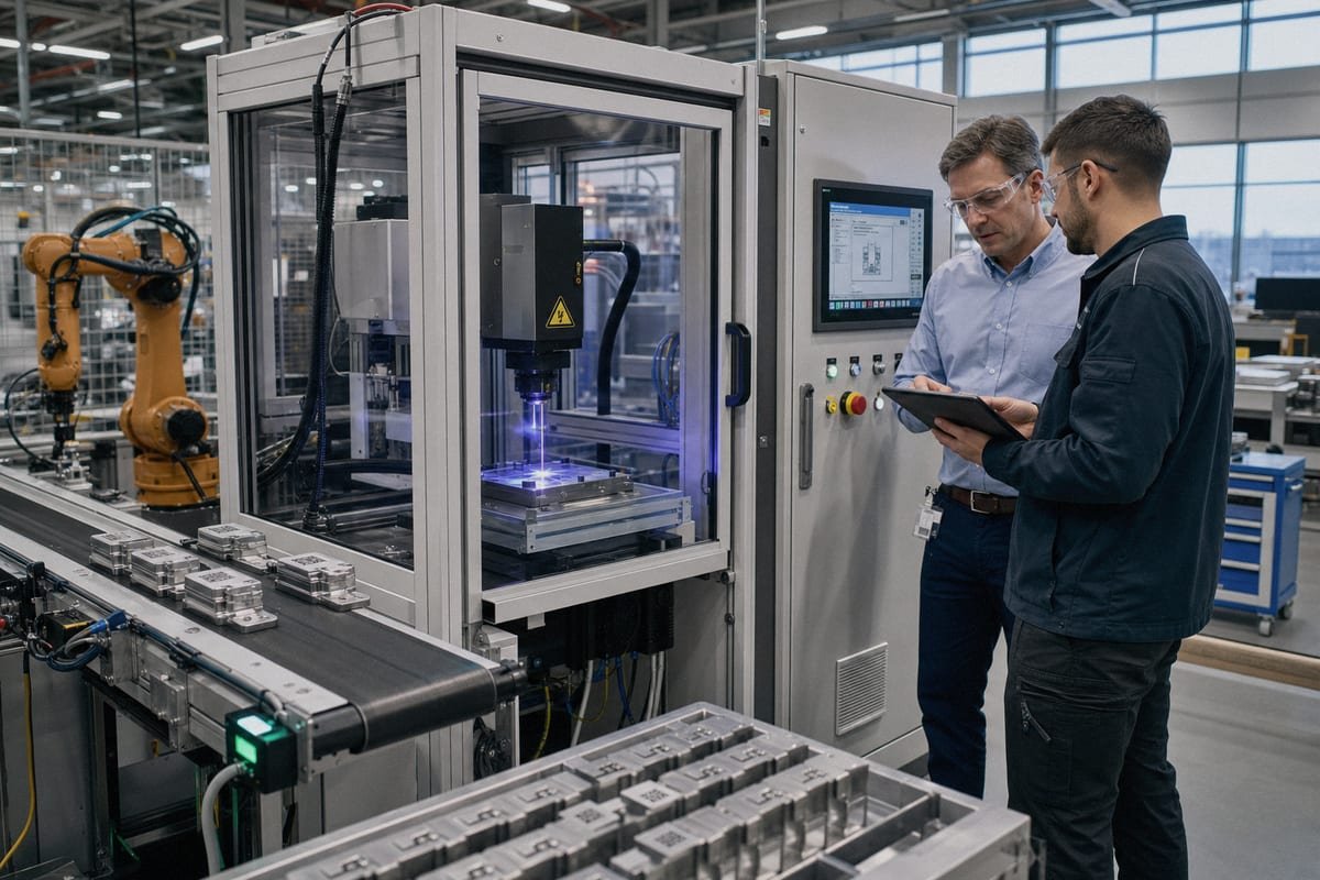
Specifications only mean something when they trace back to a production need. Below is how I translate line realities into numbers on a spec sheet.
Translate Throughput into Numbers
Vague goals like "fast enough" cause disputes later. Write measurable targets instead:
- State your parts per minute, current and projected.
- Calculate the maximum allowed marking time per part.
- Add load, position, and unload time to get the full station cycle.
- Leave a buffer of roughly 15–20% for line stoppages and variation.
- Decide between static marking and marking-on-the-fly for conveyor lines.
Marking-on-the-fly needs encoder feedback to track conveyor speed. Static marking needs a stable fixture or rotary indexer compatibility if you mark multiple faces of cylindrical parts.
Match Field, Spot, and Precision
| Specification | What It Controls | Requirement Guidance |
|---|---|---|
| Marking field | Maximum content area | Size to your mark, not larger |
| Spot size | Fine detail and code cell quality | Smaller field lenses give finer spots |
| Repeatability | Mark position consistency | Critical for automated fixtures |
| Duty cycle | Continuous operation capacity | Industrial lines need 24/7 rating |
| Cooling | Thermal stability | Air-cooled fiber suits most factories |
One caution from our engineering team: do not request an oversized field "just in case." A 300mm lens on a job needing 100mm sacrifices spot quality, code readability, and marking speed. Also budget for a fume extraction system 6 in the spec, because marking residue degrades lenses and can violate workplace air rules. Environmental items like stable power supply and ambient temperature limits belong in the requirements document too, not as afterthoughts during installation.
How Can I Ensure the Laser Marking Machine Integrates Smoothly with My Existing Automation System?
An automotive parts customer in Mexico once taught me a lasting lesson. Their machine worked perfectly in isolation, but the line stopped mid-mark during a jam, and half-marked parts slipped downstream. We rebuilt the handshake logic together, and I have specified stop-behavior ever since.
Ensure smooth integration by defining PLC communication protocols, sensor and encoder triggering, MES data exchange for variable content, vision inspection integration for mark verification, laser safety enclosure requirements, and explicit line-stop behavior. Then validate everything with dry runs before live production begins.

Integration is where a good machine becomes a good station. I recommend writing this part of your requirements as a communication map: every signal in, every signal out, and every failure case.
Define the Signal Chain
Your marking station must talk to the line in real time. Specify these items explicitly:
- Trigger source: photocell, proximity sensor, or PLC command.
- Handshake logic: ready, busy, done, and fault signals in both directions.
- PLC communication protocols: confirm whether your line uses EtherNet/IP, Profinet, Modbus TCP, or simple I/O, and require the marker's controller to match.
- Encoder synchronization: mandatory for marking-on-the-fly so mark position tracks conveyor speed.
- Line-stop behavior: define what happens if the conveyor halts mid-mark. The system should abort or complete safely, and flag the part.
Plan Data and Verification
Modern part traceability standards demand more than a visible mark. Your requirements should state how variable data flows: serial numbers pulled through MES data exchange, date codes generated locally, or batch data pushed by the PLC. If you must meet Data Matrix 7 readability grades, add vision inspection integration downstream so every code is verified and failures are rejected automatically. Regulated sectors should name their standard in the spec, such as UDI-style serialization for medical devices.
Do Not Skip Safety and Commissioning
A Class 1 laser safety enclosure lets operators work beside the station without protective eyewear, which is the norm for automated lines. Include interlocked doors, an emergency stop tied into the line's safety circuit, and fume handling. Finally, require dry-run commissioning: run the full line with unmarked parts, tune trigger timing, and simulate stoppages before the first production shift.
Conclusion
Vague requirements create expensive surprises. Define your mark, material, 300mm×300mm size limit, cycle time, laser type, and integration signals first, then talk to suppliers with confidence.
Footnotes
1. Provides technical data on how different materials conduct heat, which affects laser marking parameters. ↩︎
2. Explains the galvanometer-based scanning technology used to direct laser beams in marking machines. ↩︎
3. Updated official Aluminum Anodizers Council URL using hyphens instead of underscores. ↩︎
4. Overview of machine vision systems used to verify mark quality and data accuracy in automation. ↩︎
5. Technical definition of focal length and its relationship to spot size and laser precision. ↩︎
6. Explains the importance of removing airborne contaminants produced during the laser marking process. ↩︎
7. Official GS1 standard for Data Matrix codes, essential for industrial part traceability and serialization. ↩︎