

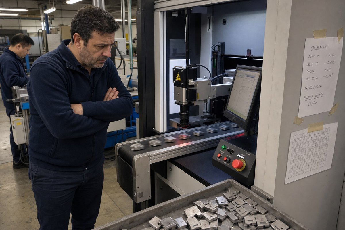
Last year, a buyer told me his CCD automated laser marking machine kept missing parts at full line speed sub-pixel edge detection 1. Misaligned marks meant scrapped batches and angry customers. At our Dongguan factory, we solved this exact problem for his line.
Yes, CCD automated laser marking machine positioning accuracy meets high-speed production needs when properly configured. Typical systems achieve ±0.02mm to ±0.1mm accuracy at full line speed, but success depends on camera trigger timing, image processing speed, conveyor synchronization, and validated dynamic repeatability testing.
The short answer is yes, but with conditions. Let me walk you through what those conditions are, how the numbers really work, and how to test any machine before you pay for it.
How accurate is CCD positioning when my production line runs at maximum speed?
During a recent factory acceptance test for a client in Italy, we ran his conveyor at its true maximum speed, not the comfortable demo speed. That distinction changed everything about the results we recorded.
At maximum line speed, a well-tuned CCD system holds ±0.02mm to ±0.1mm positioning accuracy. However, dynamic accuracy is always lower than static accuracy, so you must verify repeatability at your real production speed, not at slow demonstration speeds vendors prefer to show.
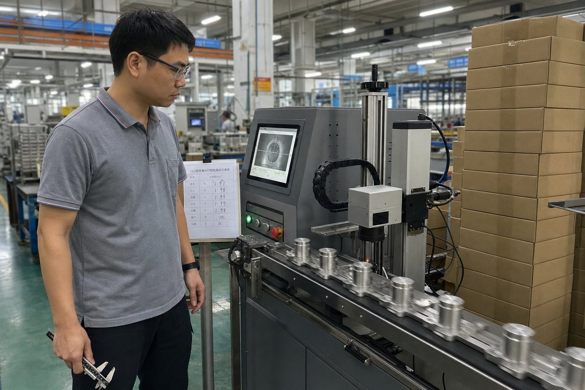
Static accuracy is what most spec sheets show. The part sits still, the camera takes a clean image, and the laser fires. Dynamic accuracy is what your line actually experiences. The part moves, vibration exists, and lighting changes as the conveyor runs. These two numbers are not the same. In our experience, the gap between them is where most buyer disappointment comes from.
Static vs. Dynamic Accuracy
Here is how the two conditions typically compare in real production settings:
| Condition | Typical Accuracy | What Affects It |
|---|---|---|
| Static (part stopped) | ±0.02mm | Industrial camera resolution, lens, calibration |
| Dynamic (part moving) | ±0.05mm–±0.1mm | Trigger delay, encoder sync, vibration |
| Dynamic + rotation offset | ±0.1mm or wider | Algorithm speed, template quality |
The key term you should demand from any supplier is dynamic repeat positioning accuracy. This is the machine's ability to hit the same spot, part after part, while the line runs at speed. Marking repeatability under motion matters far more than a single perfect static test. We always tell buyers to write the dynamic figure into the purchase contract.
There is one more nuance. Some vendors quote repeatability as low as ±0.001mm. Treat those numbers carefully. Repeatability and absolute accuracy are different metrics, and marketing pages often blur them. Repeatability tells you consistency. Absolute accuracy tells you distance from the true target. For traceability and serialization work, such as marking serial numbers on medical devices or battery components, you usually need both figures verified on your own parts.
Can CCD vision systems keep up with high-volume automated marking without sacrificing precision?
One trade-off our solution engineers weigh on every project is speed versus image quality. A faster shutter needs stronger lighting. A bigger field of view lowers pixel resolution. Every choice pulls against another.
Yes, modern CCD vision systems handle high-volume automated marking without losing precision. On-the-fly marking, fast image processing software, and multi-template management let systems process parts continuously on moving conveyors, saving three to five times the handling time of fixture-based workflows.
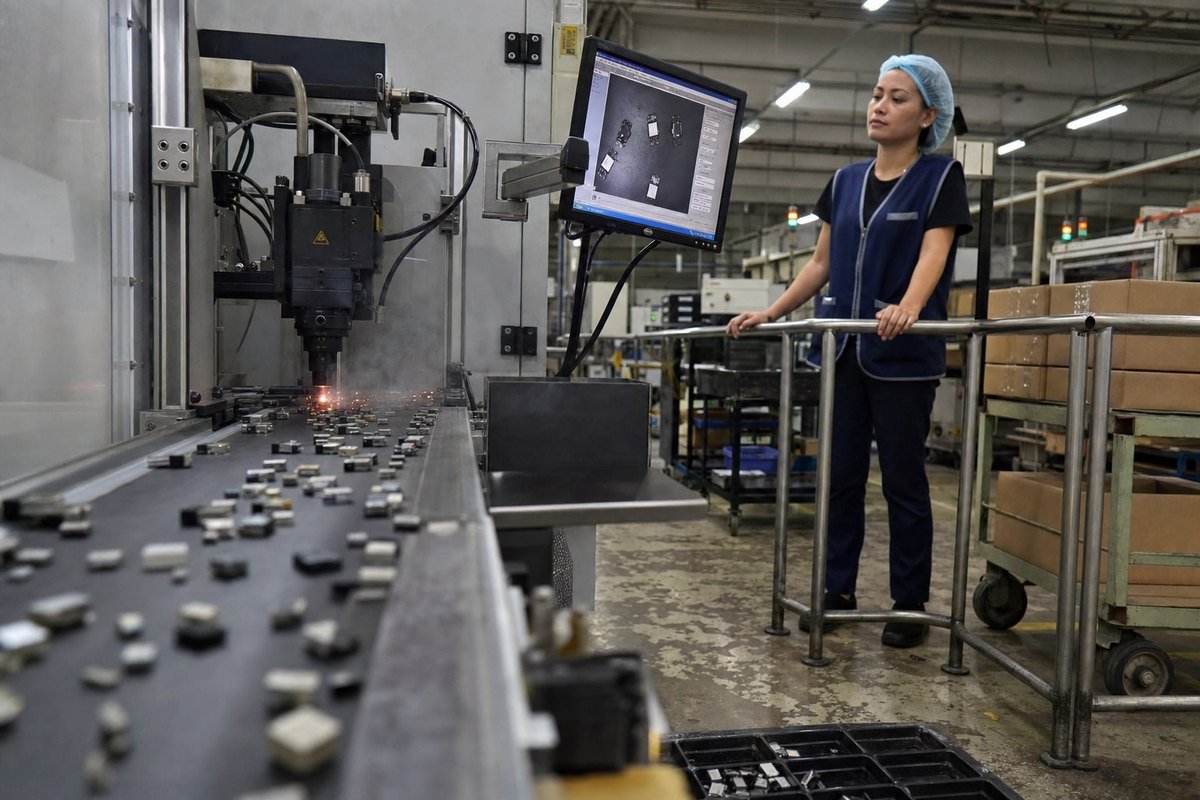
The real bottleneck in high-volume marking is rarely the laser itself. A fiber laser 2 can mark a code in under a second. The bottleneck is everything around it: part loading, alignment, and unloading. This is exactly where vision-guided laser marking earns its cost. Parts can arrive in random positions and rotations, and the camera corrects X, Y, and theta offsets automatically. No jigs. No manual placement. No operator squinting at alignment marks.
Where the Time Savings Come From
We built a CCD line for a hardware tools client who previously used fixtures. Here is where his cycle time reduction actually happened:
| Workflow Step | Fixture-Based Method | CCD Vision Method |
|---|---|---|
| Part placement | Precise manual loading | Random placement on belt |
| Alignment | Mechanical jig, operator check | Automatic X/Y/theta correction |
| Changeover | Swap and re-align fixtures | Load new software template |
| Mixed batches | Separate runs per part type | Multi-template auto-recognition |
| Rework rate | Higher from placement errors | Lower, vision verifies position |
Multi-template management deserves special mention. On mixed-batch lines, the image processing software identifies which part type just arrived and switches marking files instantly. For our clients running auto parts 3 or electronic components in varied lots, this feature alone justified the upgrade.
Precision holds up under volume because fiducial mark 4 recognition and sub-pixel edge detection let the system locate features more finely than the raw sensor resolution suggests. Combined with encoder-synced motion control systems 5, the laser fires at exactly the right moment even while the part moves. Throughput optimization and precision are not enemies here. They are engineered together.
What factors affect CCD positioning accuracy in fast-paced manufacturing environments?
A lesson we learned the hard way: a client's machine passed every test in our workshop, then drifted on-site. The cause was factory lighting that changed with the afternoon sun through a skylight. Environment matters.
Five main factors affect CCD positioning accuracy at speed: camera trigger and processing latency, lens and field-of-view selection, lighting stability, calibration drift from heat, and conveyor synchronization. Each one can silently erode accuracy even when the camera itself performs perfectly.
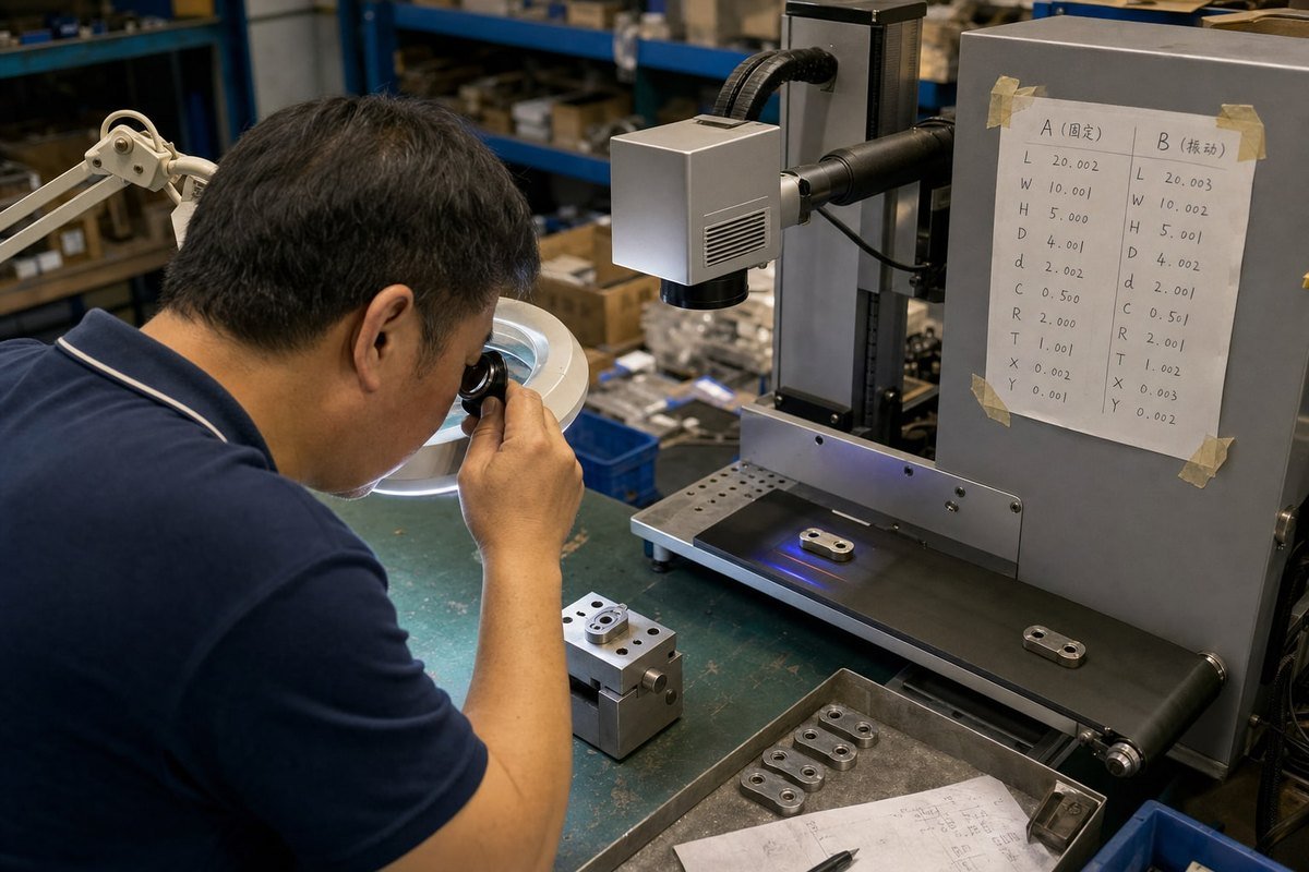
Accuracy is a chain, and the weakest link sets your real performance. Let me break the chain into its links so you can inspect each one on any machine you evaluate.
The Accuracy Chain, Link by Link
| Factor | How It Hurts Accuracy | How to Control It |
|---|---|---|
| Trigger and compute latency | Part moves during processing, mark lands late | Fast sensors, FPGA acceleration, latency testing |
| Field of view vs. resolution | Large field spreads pixels thin | Match industrial camera resolution to part size |
| Lighting variation | Edges blur, template match fails | Enclosed lighting, fixed LED sources |
| Thermal drift | Heat shifts galvo mirrors over hours | Periodic fiducial recalibration checks |
| Conveyor sync errors | Encoder slip misplaces the mark | Quality encoders, tight motion control systems |
Two of these deserve extra attention. First, latency. Between the camera trigger and the laser firing, the software must capture, process, and compute coordinates. On ultra-fast lines, advanced units use FPGA hardware 6 to make this calculation nearly instantaneous. On slower hardware, a moving part can travel a measurable distance during that delay. Always ask your supplier to state the total trigger-to-fire latency, then multiply it by your belt speed. That gives you the built-in offset the software must compensate for.
Second, thermal drift. High-speed operation heats the galvanometer head 7. Mirrors shift by microns, and marks slowly wander off target over a long shift. Better systems run closed-loop correction: they periodically image a fiducial mark and recalibrate the coordinate system without stopping the line. Some emerging setups even add real-time visual inspection of finished marks, reading grayscale contrast to flag laser power decline or lens contamination before defects appear. When we design lines for continuous three-shift operation, we treat these compensations as mandatory, not optional.
How do I test if a CCD laser marking machine meets my speed and accuracy requirements before buying?
Whenever an overseas buyer asks us for a video demo, we suggest something stronger: send us your real parts, and we run a recorded acceptance test at your true line speed. Honest suppliers welcome this.
Test before buying by running your actual parts at true maximum line speed, deliberately offsetting and rotating workpieces, measuring dynamic repeat accuracy, verifying camera trigger and processing latency, and running an extended continuous trial of several hours to expose thermal drift.

A demo at half speed with perfectly placed samples proves nothing. Over years of shipping machines to markets like the USA, Germany, and Southeast Asia, we have refined a five-step validation protocol. I recommend you demand every step from any supplier, including us.
The Five-Step Pre-Purchase Validation Protocol
-
Define dynamic repeat accuracy in writing. Ask for the repeatability figure measured while parts move at line speed. Get it in the contract, with the measurement method specified. Do not accept a static bench number as a substitute.
-
Run continuous samples at your true maximum speed. Not the demo speed. Not average speed. Set the conveyor to the fastest rate your line will ever run, then mark a large continuous batch and measure position error across all of them.
-
Deliberately offset and rotate workpieces. Place parts crooked. Shift them off-center. Flip their angle. A real production line never delivers perfect presentation, so the fiducial mark recognition and template matching must recover every deviation you throw at it.
-
Verify camera trigger and computation latency. Ask for the measured delay between trigger and laser fire. Then check whether marks stay centered as speed increases. Growing offset at higher speed exposes a latency problem.
-
Run a long, uninterrupted trial. Several hours minimum. This exposes thermal drift, lighting sensitivity, and software stability that a ten-minute demo hides completely. Sample marks throughout and chart the position error over time.
If a supplier resists any of these steps, treat that as your answer. When our engineers record these tests for clients on WhatsApp video calls, we mark the client's own products, at the client's stated speed, with time stamps visible. That transparency also solves a second worry many buyers carry: supplier authenticity. A factory that lets you watch the hard test has nothing to hide.
Conclusion
Missed marks at high speed waste parts and trust. The fix is validation. CCD positioning accuracy meets high-speed needs, but only proven systems, tested on your parts, deserve your order.
Footnotes
1. Explains the mathematical methods used to locate boundaries within digital images. ↩︎
2. Explains fiber laser technology referenced as the fast marking source in high-speed lines. ↩︎
3. Department of Commerce resource regarding the automotive industry and manufacturing standards. ↩︎
4. Technical definition of fiducial markers used for reference in machine vision systems. ↩︎
5. Comprehensive overview of motion control technology in automated industrial environments. ↩︎
6. Background on FPGA hardware clarifies how it enables near-instant latency calculations. ↩︎
7. Authoritative encyclopedia entry on optical scanners and galvanometer systems used in laser marking. ↩︎